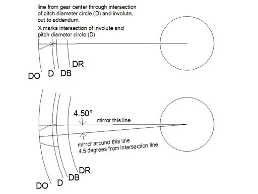
Involute gear spur pt
Table of Contents
Table of Contents
Involute gears are an essential part of many machines, but drawing them can be quite challenging for those who are new to mechanical drawing. In this article, we will explore some of the best practices for drawing involute gears in CAD or by hand, and share tips and tricks to make the process easier and more efficient.
Pain Points of Drawing an Involute Gear
Drawing involute gears can be a time-consuming and challenging process that requires precision, skill, and knowledge of gear geometry. Most people find it difficult to create the right tooth shape, maintain the right dimensions, and ensure the gear teeth mesh properly. Other challenges include properly calculating the pressure angle, pitch diameter, and tooth thickness.
How to Draw an Involute Gear
To draw an involute gear, start by selecting a standard gear size that matches your project specifications. Then, use a gear tooth thickness calculator to calculate the tooth thickness and add it to your drawing. Next, draw a base circle that matches the pitch diameter and create an involute curve using a specialized gear drafting tool or by hand. Use this curve to create the gear tooth profile, and then extrude it to form the final gear shape. You can also use gear design software like SolidWorks or AutoCAD to automate the process and create more complex gear shapes.
Summary of Main Points
In this article, we learned that drawing an involute gear can be challenging due to the need for precision, knowledge of gear geometry, and the various calculations involved. However, a great way to overcome these challenges is to use specialized gear drafting tools or software that automates the process. By following a few simple steps, you can create accurate and precise involute gears that will work seamlessly with your project requirements.
How to Draw an Involute Gear - Step by Step
When I first started drawing involute gears, I found it challenging to get the right tooth shape and dimensions. However, over time, I discovered a few tips and tricks that made the process easier and more efficient.
First, I always start by selecting a standard gear size and use a gear tooth thickness calculator to calculate the tooth thickness. Then, I draw a base circle that matches the pitch diameter and create an involute curve using a specialized gear drafting tool or by hand.
Next, I use the involute curve to create the gear tooth profile and add the root and tip clearance. Finally, I extrude the tooth profile to create the gear shape and check it for proper tooth mesh and dimensional accuracy. Using CAD software like SolidWorks or AutoCAD can automate the process and make it much faster.
Exploring Gear Teeth Geometry and Pressure Angle
One of the critical aspects of drawing an involute gear is understanding gear teeth geometry, such as pitch diameter, number of teeth, addendum, dedendum, and tooth thickness. It’s also essential to consider the pressure angle, which is the angle formed between the line of action and the tangent to the pitch circle at the point of contact. Typically, the pressure angle is 20 degrees, but it can vary depending on the type of gear and application.
Choosing the Right Gear Design Software
When it comes to designing more complex gears or creating a large number of gears, it’s best to use specialized gear design software like SolidWorks or AutoCAD. These programs can automate the entire gear design process and make it easier to visualize the gear shape, create custom gears, and adjust gear parameters in real-time.
Involute Gear Q&A
Q: How do I calculate the module of an involute gear?
A: The module of an involute gear is simply the ratio of the pitch diameter to the number of teeth. You can use a gear tooth thickness calculator or gear design software to calculate the module automatically.
Q: What is the difference between a spur gear and a helical gear?
A: A spur gear has teeth that are parallel to the axis of rotation, whereas a helical gear has teeth that are at an angle to the axis of rotation.
Q: Can I draw an involute gear by hand?
A: Yes, you can draw an involute gear by hand using specialized gear drafting tools like a gear tooth caliper, compass, and straightedge. However, it’s best to use CAD software or a gear design tool to ensure accuracy and precision.
Q: What is the best way to ensure proper tooth mesh of an involute gear?
A: The best way to ensure proper tooth mesh of an involute gear is to use a specialized gear design tool or software that can visualize the gear shape and simulate motion. You can also use a tooth contact analysis tool to check the contact stress and wear pattern of the gear teeth.
Conclusion of How to Draw an Involute Gear
Drawing an involute gear can be challenging, but with the right tools, knowledge, and skills, you can create accurate and precise gears that will work seamlessly with your project requirements. Whether you choose to draw the gear by hand or use specialized software, the key is to understand gear geometry, calculate the critical parameters, and ensure proper tooth mesh and dimensional accuracy. Happy gear-drawing!
Gallery
The Involute Curve, Drafting A Gear In CAD And Applications

Photo Credit by: bing.com / drawing gear involute spur sketch draw tooth profile curve cad drafting steps pinion rack pitch paintingvalley circle conjugate complementary given
Involute Gears

Photo Credit by: bing.com / involute drawing spline gears standards curves method asa pitch mechanical fig teeth angle pressure machinery chestofbooks practice v2 crafts
Figure 2-0 Involute Circle | Mechanical Engineering Design, Spur Gear

Photo Credit by: bing.com / involute gear spur pt
Patent EP2397243A1 - Form Rolling Method For Involute Gear - Google Patents

Photo Credit by: bing.com / patents involute
Resultado De Imagem Para Involute Gear Design Geometry | Wood Diy

Photo Credit by: bing.com / gears gear involute geometry spur diameter circle autodesk clock pt google inventor gif train 3d


